Chitika

Friday, August 26, 2011

Mold design project July 2011

In summer 2011 I have designed a Mold of the Main body of the Oxygen inhaler.
I share my knowledge and difficulties that I faced while designing the Mold.

Product Information:  Component is the main body of the oxygen inhaler used by Indian army at high altitude like kargil and Siachin Glacier. The body is assembled with the three way valve and the mouth piece ( molds of both is designed by my colleagues). body consist of the three side holes on one side and two on another side.After analyzing the part I decide to put the combination of GATE on the part- PIN GATE and MODIFIED DIAPHRAGM GATE, and hence I have to design a three plate mold.
Since the Part is hollow from inside so I decided to do a sleeve ejection.

MATERIAL: NYLON 6 FOOD GRADE.


Saturday, June 4, 2011

Material selection in Plastic part design

The decision to use plastic rather than wood, aluminum, or steel will have consequential
results on the shape, manufacture, cost, and end-use of the product. As such, product
designers should consider what properties are truly required in a given application when
developing plastic parts. Selection of an appropriate plastic material is vital in product
development since the properties of the plastic are closely tied not only to the product design but also the mold designs and process optimization. Inappropriate material selection may incur
severe costs and delays late in the product development cycle  related to trying
different materials and product redesigns.
 Following Plot shows you the comparison between yield stress and elastic properties of plastic parts and metal:

At first look it seems that plastics can't compete with other plastic except in the cost consideration.

"While plastics have low elastic modulus and yield strength compared to steel, aluminum,
titanium, magnesium, and other alternative materials, their use in structural applications can be
justified due to their low density and high strain to failure. "

Design of plastic parts-Mold design


Design of Plastic Part_Mold Design

Plastics provide many amazing advantages and property characterstics when used in Product design. From cost consideration, plastics offer not only a low cost per unit volume of material, but also low manufacturing cost, you thought that inspite of such amazing property used it is not yet as popularize as it should, that is because the some of mechanical properties limitation of the plastic parts, but researchers continously working to improve its mechanical and heat resistance property so that it replaces the metal parts in many application.
Some advantages that plastic part offer over metal or any other engineering material are as follow:
  • Light weight.
  • easy of recyclability.
  • wide range of color avalability.
  • good asthetic properties.
  • good chemical and wear property.

After we take a decision of designing the plastic part, the product development team follows the  structured methodology shown in the following snapshot.


Tuesday, May 17, 2011

MOLD ENGINEER’S RESPONSIBILITIES


                  MOLD ENGINEER’S RESPONSIBILITIES


1.      Receive estimate product drawing and data from customer and R&D.
2.      Mold design review by all Mold designer.
3.      Issue mold Design Review Sheet to PPC and Machining department.
4.      Check product drawing and data (check surface data, undercuts[have or not], surface error[have or not].
5.      Fix Numerical Control Start Point(NCSP)  and input shrinkage by Catia or other CAD packages.
6.      Reverse parting line, check point from CAM, or compare with Design Data.
7.      Make Mold concept drawing.
8.      Join in estimate meeting with concern people.
9.      Make mold base drawing, part list, issue to PPC for order.
10.  Receive new product drawing and product data from customer and R&D.
11.  Check product drawing and repeat 3, 4, 5 steps.
12.  Update drawing in CAD software:
Ø Project View .
Ø Section view.
Ø Decide injection Pin position.
Ø Core cooling design.
Ø Separate core part details.
Ø Details of 2D electrodes.
Ø Detail ejector plates.
13.  Join new mold meeting.
14.  Issue complete drawing to concern personnel.
15.  Issue 100% part list  and 100% parts.
16.  Make mold data check sheet and then give to machining and PPC department.
17.  Follow all schedule as per manufacturing schedule.
18.  Go to trial with PPC and finishing personnel.


Rapid prototyping systems classification

In the current market place there are three types of RP systems are manufactured:
LIQUID BASED SYSTEM:
-Uses the material in the liquid state like photo curable liquid resin etc.
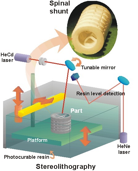
  1. 3d systems' Stereolithography  Apparatus(SLA).
  2. Cubital's Solid ground Curing.(SGC)
  3. Sony's Sollid Creation system.(SCS)
  4. Mitsubishi's Solid object Ultraviolet-laser plotter(SOUP)
  5. EOS's Stereos systems
  6. Teijin Seiki's Solidform System
  7. Meiko's Rapid Prototyping System for the Jewellery Industry.
  8. Mitusui's COLAMM
  9. Light Sculpting.

    SOLID BASED SYSTEMS:
    Expect for powder solid based systems are meant to use all forms of material in the solid state.
    1. Helisys' laminated Object Manufacturing(LOM)
    2. Stratasys' Fused Deposition modeling.(FDM)
    3. KIRA's Selective Adhesive and Hot Press.(SAHP)
    4. Kinergy's Rapid prototyping Inc.'s Model Maker MM-6B.
    5. 3D systems' Multi Jet Modeling System(MJM)
    6. IBM's Rapid prototyping system(RPS)\
    POWDER BASED SYSTEMS:
    1. DTM's Selective Laser Sintering.(SLS)
    2. Soligen's Direct Shell Product Casting.(DSPC)
    3. Fraunhofer's Multiphase Jet Solidification(MJS)
    4. EOS's EOSINT Systems.
    5. BPM Technology's Ballistic Particle Manufacturing(BPM)
    6. MIT's 3-Dimensional  Printing(3DP)

    Rapid prototyping principles and fundamntals

    As we already know increase in the CAD/CAM/CAE technology, the new manufacturing technology has emerged known as Rapid prototyping.
    There are basically three ways by which any product or component made by subtractive process, formative process and additive process.
    1. Subtractive process: Machining like milling, turning, grinding, EDM, ECM etc in which we remove material from the blank.
    2. Formative process: Bending, forging, drawing, extruding, injection molding, casting etc. to form the given material into desired shape.
    3. Additive process. This is new technology in which we add material to form 3D component. Rapid prototyping is the one of the additive process .

     Three basic steps of rapid prototyping :

    1. generation of CAD model of the component to be made using any solid modeling software like Catia, Creo element/pro, solidworks, Maya, 3ds max.
    2. Conversion of the CAD file into file format known as .STL(STereoLithography) which originates from 3d systems. The STL file approximates the surface of the CAD model by Polygons , the process is known as Tessellation.
    3. A computer analyses an .STL file and SLICES the model into cross sections. The cross sections are systematically recreated through solidification of either liquid, solid particles or powder.

    Tuesday, February 8, 2011

    Who am I?

    Welcome to my blog,I made this blog for sharing my knowledge and projects to my friends and to the world.
    I am engineering student doing engineering in Tool and die making from Delhi in Delhi Institute of Tool engineering.This is my first blog and so please ignore my mistakes.
    What I posted on this BLOG?
    Some knowledge which I earned from my college and I will earn in the future.
    My specialized Topic in which I think I can post some thing are:

    MOLD DESIGNING, PRESS TOOL DESIGN,  DIE DESIGN,  RAPID PROTOTYPING, CAD/CAM/FEM.
    One thing I want to tell you that beside engineering my hobiesy is to play with photos, collecting wallpapers from the Internet So I made website on that http://www.wallapersondemand.org
    If some one like to see my wallpapers collection then watch out my website .